Receiver Power
For a decade and more I used four Sanyo N110 NiCd cells to power the receiver and servos. The energy used for an F5B flight I measured at 25mAhr for a two servo wing (Surprise 11) and 40 mAhr for a four servo wing (Avionik B06). So the 110 mAhr was plenty. I tried equivalent weight (30gms) NiMH with bad results. The voltage fell to dangerous levels at high (2.5A) currents, especially in cold conditions.
New NiCds became difficult to get, then in addition I had space problems in the B06. So I decided to jump to LiPo cells with a regulator. 2S LiPo packs intended for indoor flight can supply 5A with ease, and weigh 20gms. The only problem is that they need a regulator to reduce the voltage from 8.4 V to something acceptable to the radio. Switching regulators are on offer to do this, but I feared them as in the Avionik they will be hard up against the receiver and interference would be a problem. Linear regulators are available and used by some, eg Joe Mouris (Flight power) and David Hines (Thunder Tiger). But they are big and heavy and I could not see how to fit them into the Avionik. So I decided to build my own.
Commercial linear regulators are big because the designers build them for continuous operation. For F5B this is not necessary. The currents can indeed be 2.5A or more, but the total energy throughput is only max 50mAhrs in 15 minutes, an average of 200mA, generating very little heat. So a small PC board is all that is required. The one I used is 38mm x 19mm as shown below.
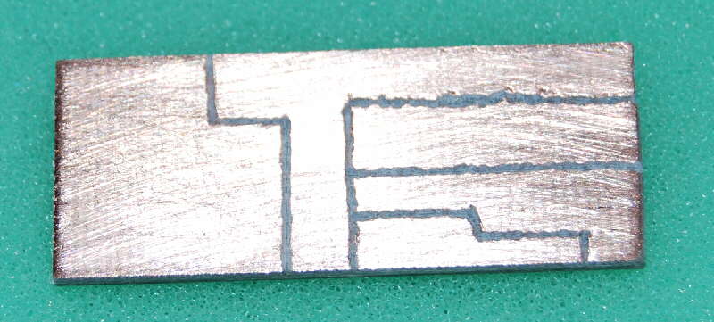
The board is double sided, but the other side is left blank to help with heat dissipation. The position of the tracks is determined by placing the regulator on the board and drawing round it with a scriber. The tracks are cut out using a grinding tool, I use a small tool sold to draw images in crystal glasses (from wife), but I think a Proxxon or Dremel would be fine. The next picture shows the components in place.
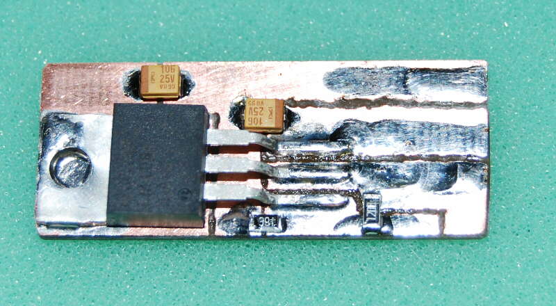
The regulator is the LM 1084 see http://www.national.com/ds/LM/LM1084.pdf R1 is 120ohm and R2 is 390ohm. This gives about 5.3V which seems fine. At 2.5A this delivers a full 5V at the receiver connection. There is space alongside the 120ohm on the circuit board to add another resistor in parallel which will increase the voltage, see the formula on the datasheet above. Below is a regulator wired up, in fact the fourth one just after testing and before kapton taping. Note that in this one there is a 2.2k resistor in parallel with the 120 Ohm one as the initial voltage was only 5.2V (resistor tolerance) and the servos on my Avionik B08 seem a bit slow, so this resistor raised the voltage to 5.4V. I am not a fan of high radio voltage for fear of brush wear in the servos.
Note that the battery is removeable for charging. In an earlier implementation I followed my NiCd practice of installing the battery permanently and having a separate charge wire, see below:
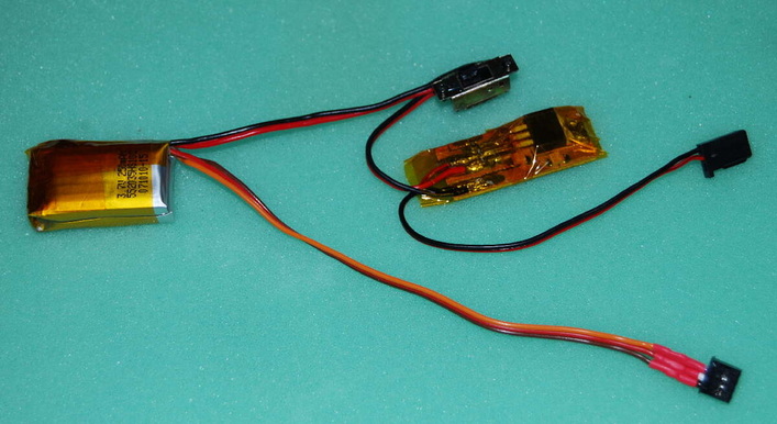
This worked fine until the model was left switched on for several days. This happened in the past with NiCd but the batteries recovered fine. Not so the LiPo. After several tries I got them to take charge again and get up to the proper voltage, but on testing at 2.5A the output voltage of one cell was way down. This required a solder job to replace. The plug and socket on the removeable battery don't seem to drop much voltage, they are used in the manufacturer's standard radio installation after all. Here they are upstream of the regulator so any voltage drop is not seen by the receiver. I just have to guard against the Mike Seale experience in Prague I think, of the battery disconnecting after a vigourous launch.
George. I'd forgotten that. It was actually Neuhardenberg (1998) and installing the flight battery must have pushed the receiver away from the receiver battery so it was only held loosely in place. The launch then disconnected it. Luckily the motor cut and the model landed reasonably softly. No damage but a zero for that round and then I had o fly more carefully for the rest of the competition. I now either hard-wire the battery to the switch or tape the connector so it can't come apart. Mike
George. I'd forgotten that. It was actually Neuhardenberg (1998) and installing the flight battery must have pushed the receiver away from the receiver battery so it was only held loosely in place. The launch then disconnected it. Luckily the motor cut and the model landed reasonably softly. No damage but a zero for that round and then I had o fly more carefully for the rest of the competition. I now either hard-wire the battery to the switch or tape the connector so it can't come apart. Mike
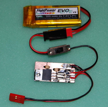
Steve Burns Regulator setup
This is the way Steve is powering his receivers now. The items used in this example are a 2s Lipo 360mAh, a safe switch which was purchased from Hyperflight in the UK and a Castle Creations BEC.
The lipo can be left connected as the power consumed by the switch is so small. Also the switch has a built in charge port.
At some point I do intend to fit a extension lead or fuselage mounted socket to the balance connector to make life easier when it comes to battery maintenance.
Link for the safe switch
http://www.hyperflight.co.uk/products.asp?code=PLD-ESJ-CHG-RX
Mike Seale's version of the regulator
Here's my example of the voltage regulator design originally published by George Shering. I've made it a little bigger than the original in order to dissipate more heat. This is probably not necessary for F5B but I plan to use these regulators in some of my sport models too and here the extra copper should give an acceptable margin of safety.
I got the double sided copper board from Maplins. This was about £5. The regulator, capacitors and resistors were purchased from Farnell. I ordered enough to make 10 regulators and this cost a total of £40. So each regulator will cost me less than £5. If you want to make your own here are the parts you'll need.
Regulator
10 uF Capacitor
120 Ohm Resistor
390 Ohm Resistor
I cut the circuit board the same size as a FlightPower 350mAh 2s lithium battery that I intend to use in my F5B models on the assumption that if the battery fits the regulator will too. The tracks were cut out using a fine tipped grinding tool on my Dremel. This took about 5 minutes. I then used a fine tipped soldering iron to place the regulator and surface mount devices. I've done a lot of soldering in the past but this was my first go with SMD's and it was surprisingly easy. Pre-tin the copper board where you want the device to go, place it in position and hold it still with the tip of the small screwdriver. Then hold the iron against one side of the device for a couple of seconds and watch the solder flow. The most difficult bit was placing them in the right place to start with, especially the resistors which are so small.
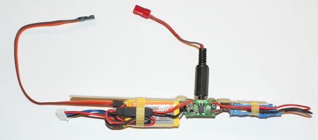
I've chosen to use micro-deans connectors on my regulator and will modify my switches harnesses accordingly. I have chosen to do this because I already use these connectors on my indoor models and it will create a safety standard for me...micro-deans = lithium, UNI = NiMH
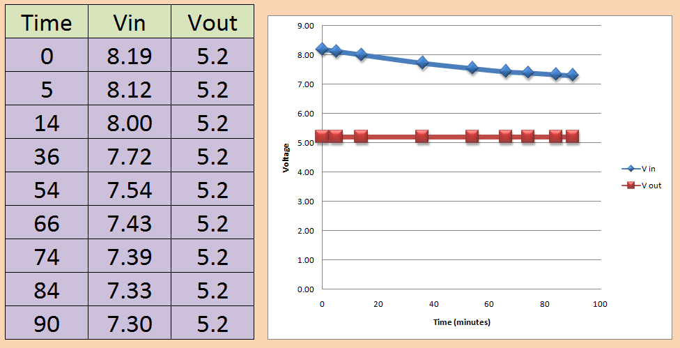
At the moment I've only had a chance for limited testing but it looks very promising. I attached a fully charged battery to the regulator and ran a single servo continuously back and forth for 90 minutes, measuring input and output voltage at regular intervals. The regulator was cold to the touch throughout. The data shows that a steady 5.2V was delivered at all times even thoguh the supply voltage was dropping the whole time. At the end of the test I recharged 179mAh indicating that the avarage current was119mA. I know that 5 servos will pull more current than one, and that they will be working harder in flight at 150mph, but these initial tests look promising.
Mike
I got the double sided copper board from Maplins. This was about £5. The regulator, capacitors and resistors were purchased from Farnell. I ordered enough to make 10 regulators and this cost a total of £40. So each regulator will cost me less than £5. If you want to make your own here are the parts you'll need.
Regulator
10 uF Capacitor
120 Ohm Resistor
390 Ohm Resistor
I cut the circuit board the same size as a FlightPower 350mAh 2s lithium battery that I intend to use in my F5B models on the assumption that if the battery fits the regulator will too. The tracks were cut out using a fine tipped grinding tool on my Dremel. This took about 5 minutes. I then used a fine tipped soldering iron to place the regulator and surface mount devices. I've done a lot of soldering in the past but this was my first go with SMD's and it was surprisingly easy. Pre-tin the copper board where you want the device to go, place it in position and hold it still with the tip of the small screwdriver. Then hold the iron against one side of the device for a couple of seconds and watch the solder flow. The most difficult bit was placing them in the right place to start with, especially the resistors which are so small.
I've chosen to use micro-deans connectors on my regulator and will modify my switches harnesses accordingly. I have chosen to do this because I already use these connectors on my indoor models and it will create a safety standard for me...micro-deans = lithium, UNI = NiMH
At the moment I've only had a chance for limited testing but it looks very promising. I attached a fully charged battery to the regulator and ran a single servo continuously back and forth for 90 minutes, measuring input and output voltage at regular intervals. The regulator was cold to the touch throughout. The data shows that a steady 5.2V was delivered at all times even thoguh the supply voltage was dropping the whole time. At the end of the test I recharged 179mAh indicating that the avarage current was119mA. I know that 5 servos will pull more current than one, and that they will be working harder in flight at 150mph, but these initial tests look promising.
Mike
