Limiter Testing
When limiters were introduced, there were many questions about their accuracy and the effect this might have on competition results.
After much discussion the FAI eventually decided in time for the 2008 World Champs that a limiter be tested in series with 2 SM UniLogs using the normal flight battery and a dummy load. The accuracy required in this test is 2%.
In the meantime, here in the UK, a testing device was built which enabled a limiter to be tested and the cut-off value recorded in a repeatable and accurate manner. This tester was ready for the start of the 2008 season so the UK team could be sure they were complying with the rules.
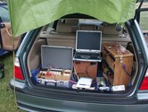
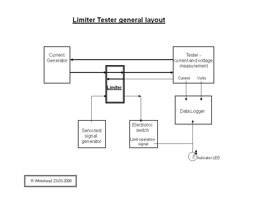
To allow many limiters to be tested quickly on the flying field, our tester was built using the principle of separating the voltage and current circuits. This method of testing is quite common in heavy current electrical engineering. A low voltage high current circuit is used coupled with voltage injection from a low power source. This meant that only about 200 watts is needed to power the tester instead of around 2000 watts for the conventional setup.
The current is adjustable in steps from about 100A up to about 230A, and can be pulsed like F5B or continuous like F5D. The voltage is selectable to simulate 3s to 6s Lipos.
For those interested, the technical details and diagrams can be viewed by following this link.
Close tolerance components were selected (some with a calibration certificate) and much time was spent calibrating other critical parts. If possible, 2 different methods of calibration were used to confirm the results. The tester was designed to have an accuracy of better than +/-1%.
Over the 2008 season, 16 different Neu, SM, and George Shering, limiters have been tested – some several times. All of these recorded errors of less than +/- 1% on the tester. The maximum difference between repeat tests of the same limiter is less than 0.5%.
Diagrams for Limiter Tester
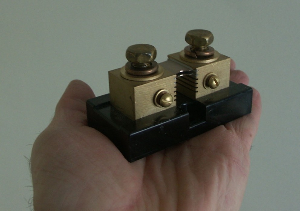 Current Shunt
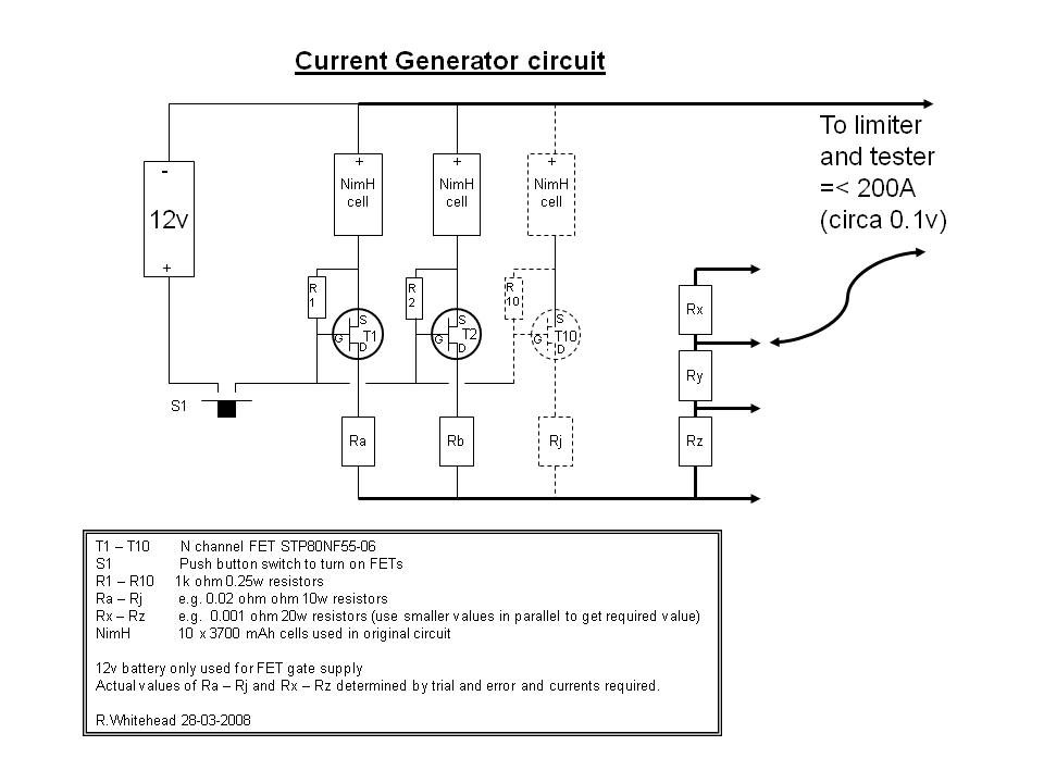
10 NimH cells are used in parallel to circulate up to 230 amps through the limiter, and the voltage is provided by a small variable voltage regulator. The NimH cells are charged in a separate "charging box" so that one set of cells can be in use while the other is being recharged. In this way testing can be continuous e.g up to 10 per hour for many hours.
The current is switched by a bank of FETs so it can be pulsed like F5B or continuous like F5D. Current is selectable from 100A up to about 230A, and voltages to simulate 3 to 6 s Lipo. Different voltages and currents can be set up if required.
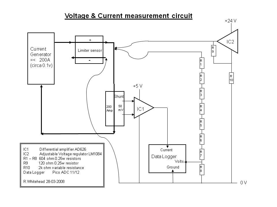
The current is measured by passing it through a close tolerance (+/- 0.25%) fan cooled current shunt which is connected via an amplifier to a multi channel data logger.
The voltage is measured via a voltage divider also connected to the data logger. The data logger has a calibration certificate, and the amplifier and voltage dividers were calibrated using a 10m long bridge circuit, with a “Time Electronics milli-volt source” also used to confirm the measurements. High accuracy (+/- 0.04%) time and voltage reference signals are also supplied to the data logger as a check on correct operation.
The current is switched by a bank of FETs so it can be pulsed like F5B or continuous like F5D. Current is selectable from 100A up to about 230A, and voltages to simulate 3 to 6 s Lipo. Different voltages and currents can be set up if required.
The current is measured by passing it through a close tolerance (+/- 0.25%) fan cooled current shunt which is connected via an amplifier to a multi channel data logger.
The voltage is measured via a voltage divider also connected to the data logger. The data logger has a calibration certificate, and the amplifier and voltage dividers were calibrated using a 10m long bridge circuit, with a “Time Electronics milli-volt source” also used to confirm the measurements. High accuracy (+/- 0.04%) time and voltage reference signals are also supplied to the data logger as a check on correct operation.