CC125 failures are discussed a lot in F5B. Anecdotal evidence is that heating is a culprit or contributing factor. One component which gets very hot is the voltage regulator on the top left of the control board as shown below.
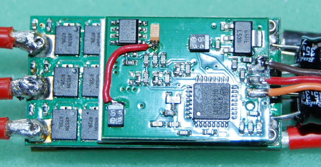
To verify this connect the CC125 up outside the plane and put your finger on this regulator. This regulator supplies all the internal electronics for the controller, including the voltage doubler which provides the drive to the main FETs. Additional heating of the CC125 due to doing real work adds to the base temperature of this regulator. Also running on 6S increases its dissipation and hence temperature. If all this adds up to a too high temperature the regulator may reduce its output voltage to protect itself. This will reduce the drive to the main FETs which increase their dissipation and hence further increase the temperature leading to runaway heating.
But the CC125 has two other, much bigger, regulators. One on the top right and one underneath. These supply the BEC which in F5B we use only to supply the limiter and opto-coupler! The red wire shown above connects all three regulators together so that they share the load. I verified this by placing my finger on the one at the top right. It got much hotter and the small one got a lot cooler. This may depend on the relative tolerances of the regulators, but certainly if the small one got worried the big ones would take over. The wire is, as shown, between the positive connection of the small regulator's output capacitor and that of one of the big regulators, both of which are connected together by the PC board.
Note that this modification does not reduce the overall heat generated, only distributes it better over the three regulators. Good ventilation is required in flight and it should not be left too long on the ground with the battery connected!
