Advanced Modification
This modification is quite complicated and should only be undertaken by a professional or advanced electronic hobbyist. It has two restrictions: firstly the use of the controller is restricted to 4, 5 or 6S; secondly it can only be applied to later controllers, those with FETs with a Vgs limit of 20V (eg 4108N "flat" FETs) , not the earlier ones where the limit was 12V, (eg 4368 "leggy" FETs).
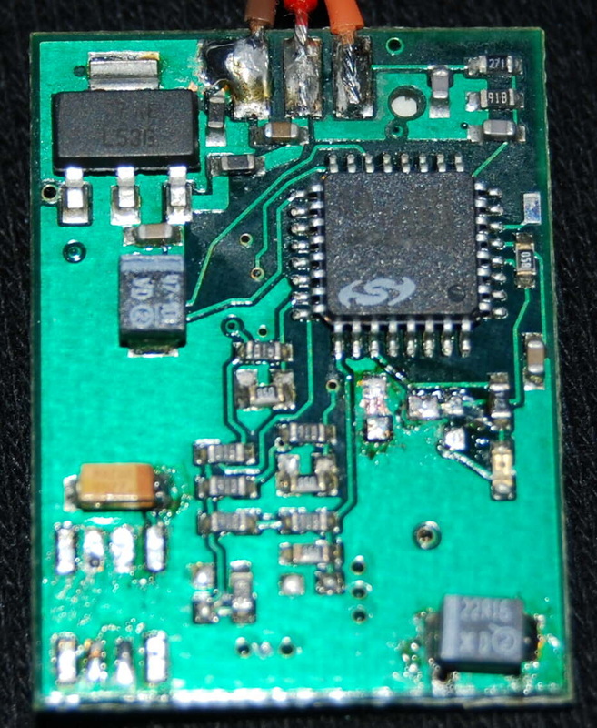
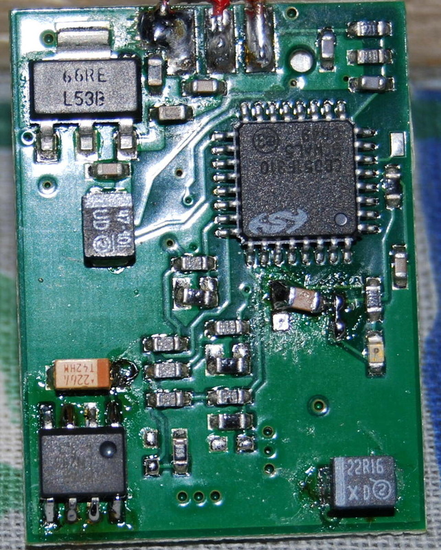
The principle of operation is to use the three regulators on the logic board for three separate functions. Normally the two big regulators are in parallel for the BEC and a small SO8 regulator provides the 5V for the controller itself. This 5V is converted to 10V by a voltage doubler to provide the power to the FET drivers and dropped to 3.3V by a resistor and Zener diode to power the microprocessor. These functions are split by the modification. One of the big regulators is retained to supply the BEC, no more than the limiter and optocoupler in F5B. The other is changed for a 12V regulator to supply the FET drivers directly. The SO8 regulator is changed for a 3.3V one to supply only the microprocessor directly. 12V is chosen for the FET driver as the newer FETs can take it, the specification for the FET drivers is 12V, and the higher drive voltage reduces the FET on-resistance by a small amount which may reduce heating and improve braking, though whether this will be noticeable in practice is not yet ascertained. This arrangement and its greater efficiency reduces the static heating of the controller by nearly a half, from 90mA to 50mA, and, the SO8 regulator heating to one third from 50-60mA down to 20mA.
The components needed for this modification are:
12V Sot-223 regulator, I ordered a NATIONAL SEMICONDUCTOR LM2937IMP-12/NOPB, Farnell part number 1469069 and got the L 74B
CAPACITOR, TANTALUM, 16V, 22UF VISHAY SPRAGUE TR3B226K016C0600 Farnell 1754089
3.3V SO8 regulator, National Semiconductor LM2936M-3.3/NOPB, Farnell 1469059
CAPACITOR, 0805, 470NF, KEMET, Farnell 1288279
The following six pictures show the steps to be taken. Clicking on each picture shows the detail.
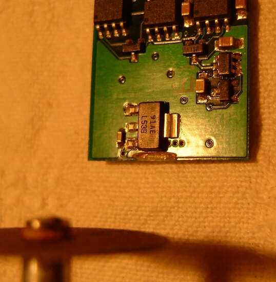
The first thing to do is to cut the link between the two SOT-223 BEC regulators. The first picture shows how Joe did this with a Dremel. The connection is on the second layer down, under the ground layer, near the bottom of the board. If the previous modification has been done remove its wire first. Before cutting plug the logic board into 5V (eg the castle link) and check the 5V at this lower output land. After cutting check that the solid 5V has gone and only 4.45 or so is there, and that the 4.45V is also present on the input one. The second picture shows how I did my first one with a glass engraving cutter, but I did not know there was a second connection so near, don't cut it, as you can see the shiny copper near in the picture.
The second picture also shows the bottom (inside) of the logic board with the 5V regulator and the two small black voltage doubling components removed. The angled decoupling capacitor is not my fault! Cut the legs of the components with a sharp knife or clippers, do not try to unsolder the component, the PCB lands are delicate and easily damaged. Components are cheap. I cut the three SOT-223 legs then unsoldered the big remaining ground tab. For the small components cut one side then bend back to break the others, or cut them too. Clean up the SOT-223 lands carefully as shown (or better). Leave the cut off legs of the small components, least risk. Examine with a magnifying glass for shorts, damage, etc.
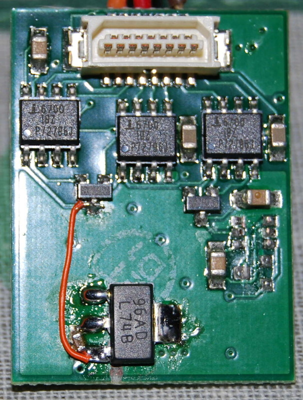
The third picture shows the top of the logic board with the capacitor removed. Replace it with the 16V one as shown on picture 4. Back to picture 3, solder on the new 12V sot-223 regulator, and the connecting wire to the FET driver inputs. The board will now work like this. What we have done is to replace the 10V from the voltage doubler by 12V directly from the SOT-223 regulator. The SO8 regulator is a lot cooler as it no longer has to supply double the FET drive current. Just as well to test it like this, ideally with a current limited supply and a high resistance motor if available.
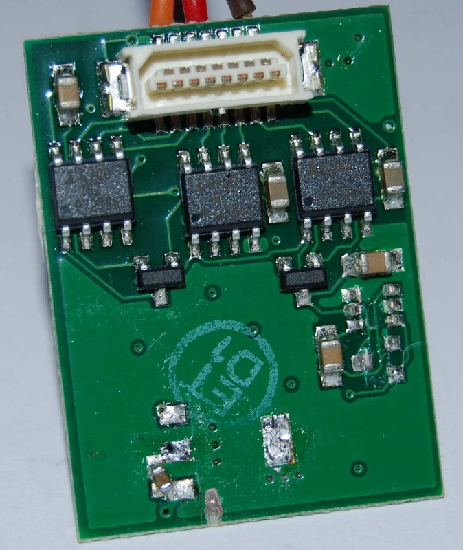
The next step is to replace the 5V SO8 regulator with the 3.3V one feeding the microprocessor directly. This cuts the current from 36mA to 20mA as excess current is required by the simple resistor-zener diode network. Picture 5 shows the SO8, zener and dropping resistor removed. Also shown is how the ground area opposite the zener input connection is scraped to give a better connection area for the decoupling 470nF capacitor.
Finally picture 5 shows the 3.3V regulator, decoupling capacitor, and bit of wire where the dropping resistor used to be. Before putting in this final bit of wire you can connect to the Castle Link and check the 3.3V. Then put the link in and the microprocessor should start flashing the LED. Job done.
The second picture also shows the bottom (inside) of the logic board with the 5V regulator and the two small black voltage doubling components removed. The angled decoupling capacitor is not my fault! Cut the legs of the components with a sharp knife or clippers, do not try to unsolder the component, the PCB lands are delicate and easily damaged. Components are cheap. I cut the three SOT-223 legs then unsoldered the big remaining ground tab. For the small components cut one side then bend back to break the others, or cut them too. Clean up the SOT-223 lands carefully as shown (or better). Leave the cut off legs of the small components, least risk. Examine with a magnifying glass for shorts, damage, etc.
The third picture shows the top of the logic board with the capacitor removed. Replace it with the 16V one as shown on picture 4. Back to picture 3, solder on the new 12V sot-223 regulator, and the connecting wire to the FET driver inputs. The board will now work like this. What we have done is to replace the 10V from the voltage doubler by 12V directly from the SOT-223 regulator. The SO8 regulator is a lot cooler as it no longer has to supply double the FET drive current. Just as well to test it like this, ideally with a current limited supply and a high resistance motor if available.
The next step is to replace the 5V SO8 regulator with the 3.3V one feeding the microprocessor directly. This cuts the current from 36mA to 20mA as excess current is required by the simple resistor-zener diode network. Picture 5 shows the SO8, zener and dropping resistor removed. Also shown is how the ground area opposite the zener input connection is scraped to give a better connection area for the decoupling 470nF capacitor.
Finally picture 5 shows the 3.3V regulator, decoupling capacitor, and bit of wire where the dropping resistor used to be. Before putting in this final bit of wire you can connect to the Castle Link and check the 3.3V. Then put the link in and the microprocessor should start flashing the LED. Job done.
